


JEE Mains · Physics · STD 12 - Semicondutor electronics
- JEE Mains 2021
- Hard
- Numerical
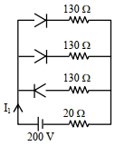
In the given figure, each diode has a forward bias resistance of \(30\, \Omega\) and infinite resistance in reverse bias. The current \({I}_{1}\) will be \(....\,A\)
Pick an option to check your answer.
Answer & Solution
Correct Answer
(C) \(2\)
Step-by-step Solution
Detailed explanation
As per diagram,
Diode \({D}_{1} \& {D}_{2}\) are in forward bias i.e. \({R}=30 \,\Omega\)
whereas diode \({D}_{3}\) is in reverse bias i.e. \({R}=\) infinite
\(\Rightarrow\) Equivalent circuit will be
Applying \(KVL\) starting from point \(A\)
\(-\left(\frac{{I}_{1}}{2}\right) \times 30-\left(\frac{{I}_{1}}{2}\right) \times 130-{I}_{1} \times 20+200=0\)
\(\Rightarrow-100 {I}_{1}+200=0\)
\({I}_{1}=2\)
More questions from Physics
- A light rope is wound around a hollow cylinder of mass \(5\,kg\) and radius \(70\,cm\). The rope is pulled with a force of \(52.5\,N\). The angular acceleration of the cylinder will be.....\( {rad \,s}{ }^{-2}\).JEE Mains 2023 Medium
- Two bodies of masses \(m_{1}=5\,kg\) and \(m _{2}=3\,kg\) are connected by a light string going over a smooth light pulley on a smooth inclined plane as shown in the figure. The system is at rest. The force exerted by the inclined plane on the body of mass \(m _{1}\) will be\(....N\) [Take \(g=10\,ms ^{-2}\) ]
 JEE Mains 2022 Hard
- Which of the following are true for a single slit diffraction?
(A) Width of central maxima increases with increase in wavelength keeping slit width constant.
(B) Width of central maxima increases with decrease in wavelength keeping slit width constant.
(C) Width of central maxima increases with decrease in slit width at constant wavelength.
(D) Width of central maxima increases with increase in slit width at constant wavelength.
(E) Brightness of central maxima increases for decrease in wavelength at constant slit width.JEE Mains 2026 Easy - Given below are two statements : Statement \(I\) : The contact angle between a solid and a liquid is a property of the material of the solid and liquid as well. Statement \(II\) : The rise of a liquid in a capillary tube does not depend on the inner radius of the tube. In the light of the above statements, choose the correct answer from the options given below :JEE Mains 2024 Hard
- The center of mass of a thin rectangular plate (fig - x ) with sides of length \(a\) and \(b\), whose mass per unit area \((\sigma)\) varies as \(\sigma=\frac{\sigma_0 x}{a b}\) (where \(\sigma_0\) is a constant), would be \(\qquad\)
 JEE Mains 2025 Medium
- In a coil, the current changes form \(-2 \mathrm{~A}\) to \(+2 \mathrm{~A}\) in \(0.2 \mathrm{~s}\) and induces an emf of \(0.1 \mathrm{~V}\). The selfinductance of the coil is _______.JEE Mains 2024 Hard
More PYQs from JEE Mains
- A uniformly tapering conical wire is made from a material of Young's modulus \(Y\) and has a normal, unextended length \(L.\) The radii, at the upper and lower ends of this conical wire, have values \(R\) and \(3R,\) respectively. The upper end of the wire is fixed to a rigid support and a mass \(M\) is suspended from its lower end. The equilibrium extended length, of this wire, would equalJEE Mains 2016 Hard
- Assume that the displacement\((s)\) of air is proportional to the pressure difference \((\Delta p)\) created by a sound wave. Displacement\((s)\) further depends on the speed of sound \((v),\) density of air \((\rho)\) and the frequency \((f)\) If \(\Delta p \approx 10\, Pa , v \approx 300\, m / s , p \approx 1\, kg / m ^{3}\) and \(f \approx 1000 \,Hz\), then \(s\) will be the order of (take multiplicative constant to be \(1\) )JEE Mains 2020 Easy
- Identify the correct statements :
A. Effective capacitance of a series combination of capacitors is always smaller than the smallest capacitance of the capacitor in the combination.
B. When a dielectric medium is placed between the charged plates of a capacitor, displacement of charges cannot occur due to insulation property of dielectric.
C. Increasing of area of capacitor plate or decreasing of thickness of dielectric is an alternate method to increase the capacitance.
D. For a point charge, concentric spherical shells centered at the location of the charge are equipotential surfaces.
Choose the correct answer from the options given below.JEE Mains 2026 Medium - A solid ball of radius \(R\) has a charge density \(\rho \) given by \(\rho = {\rho _0}\left( {1 - \frac{r}{R}} \right)\) for \(0 \leq r \leq R\). The electric field outside the ball isJEE Mains 2018 Hard