AP EAMCET · PHYSICS · Semiconductors
The logic gate equivalent to the circuit shown in the figure is
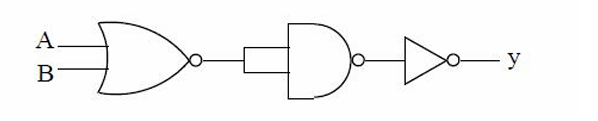
- A AND
- B NAND
- C NOR
- D OR
Answer & Solution
Correct Answer
(C) NOR
Step-by-step Solution
Detailed explanation
Output of OR gate: \( A+B \) Output of inverter: \( \overline{A+B} \) Equivalent gate: NOR
See the Complete Solution
Get step-by-step explanations for this and 2.5 Lakh+ more JEE, NEET & CET questions.
- Unlock all solutions
- Practice the full chapter
- Track accuracy across PYQs
4.8 rated on Google Play · 14,000+ reviews
More questions from PHYSICS
- A string of length \(1 \mathrm{~m}\) and mass \(490 \mathrm{~g}\) is put under a tension of \(25 \mathrm{~N}\). A wave of frequency \(120 \mathrm{~Hz}\) is sent along it. The speed of this wave isAP EAMCET 2022 Medium
- A player kicks a foot ball at an angle \(30^{\circ}\) with the horizontal with an initial speed \(30 \mathrm{~ms}^{-1}\).
A second player standing at a distance of \(21 \sqrt{3} \mathrm{~m}\) from the first and in the direction of kick. Starts running to catch the ball, at the same instant as kicked by first player. The minimum speed of second player to catch the ball before it hits the ground is
(Take, acceleration due to gravity \(=10 \mathrm{~ms}^{-2}\) )AP EAMCET 2022 Hard - If a microscope is placed in air, the minimum separation of two objects seen as distinct is 6 pm . If the same is placed in a medium of refractive index 1.5 , then the minimum separation of the two objects to see as distinct isAP EAMCET 2024 Medium
- Two identical condensers \(M\) and \(N\) are connected in series with a battery. The space between the plates of \(M\) is completely filled with a dielectric medium of dielectric constant 8 and a copper plate of thickness \(\frac{d}{2}\) is introduced between the plates of \(N\). ( \(d\) is the distance between the plates). Then potential differences across \(M\) and \(N\) are, respectively, in the ratioAP EAMCET 2011 Hard
- A copper wire of cross-sectional area \(0.01 \mathrm{~cm}^2\) is under a tension of \(22 \mathrm{~N}\). The decrease in the cross-sectional area is
(Young modulus \(=1.1 \times 10^{11} \mathrm{Nm}^{-2}\), Poisson's ratio \(=0.32\) )AP EAMCET 2018 Easy - The force per unit length on a straight wire carrying current of 8 A making an angle of \(30^{\circ}\) with a uniform magnetic field of 0.15 T isAP EAMCET 2025 Easy
More PYQs from AP EAMCET
- The locus of a point which is at a distance of 2 units from the line \(2 x-3 y+4=0\) and at a distance of \(\sqrt{13}\) units from a point \((5,0)\) isAP EAMCET 2023 Easy
- Identify antihistamines from the following:
\(\begin{array}{cccc}
\hline \text { Serotonin } & \text { Dimetane } & \text { Phenelzine } & \text { Seldane } \\
\hline 1 & 2 & 3 & 4 \\
\hline
\end{array}\)AP EAMCET 2019 Easy - The smallest integer \(n\) such that \(\frac{1}{\sin 45^{\circ} \sin 46^{\circ}}+\frac{1}{\sin 47^{\circ} \sin 48^{\circ}}+\ldots\) \(+\frac{1}{\sin 133^{\circ} \sin 134^{\circ}}=\frac{1}{\sin \left(n^0\right)}\) isAP EAMCET 2022 Easy
- The harmonic mean of two numbers is \(-\frac{8}{5}\) and their geometric mean is 2 . The quadratic equation whose roots are twice those numbers isAP EAMCET 2017 Medium
- 'Natalite' is used asAP EAMCET 2005 Medium
- In non-rigid diatomic molecule with an additional vibrational modeAP EAMCET 2022 Easy