NEET · Physics · STD 12 - 14. Semicondutor electronics
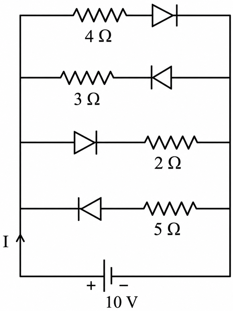
The current \(I\) in the circuit shown below is :
(All diodes are ideal and identical)
- A \(\frac{5}{3} A\)
- B \(\frac{5}{9} A\)
- C \(\frac{1}{3} A\)
- D \(\frac{15}{2} A\)
Answer & Solution
Correct Answer
(D) \(\frac{15}{2} A\)
Step-by-step Solution
Detailed explanation
(D) \(\frac{15}{2} A\)
From the given circuit, the positive terminal of the 10 V battery is connected to the left side of the parallel branches.
Therefore, the left side is at a higher potential compared to the right side.
The diodes in the branches with \(4 \Omega\) and \(2 \Omega\) resistors have their anodes connected to the higher potential side, so they are forward-biased and act as short circuits (since they are ideal).
The diodes in the branches with \(3 \Omega\) and \(5 \Omega\) resistors have their cathodes connected to the higher potential side, so they are reverse-biased and act as open circuits.
The effective circuit consists of the \(4 \Omega\) and \(2 \Omega\) resistors connected in parallel across the 10 V battery.
The equivalent resistance of the circuit is:
\(R_{e q}=\frac{4 \times 2}{4+2}=\frac{8}{6}=\frac{4}{3} \Omega\)\(B=\frac{-P}{\Delta V / V}=-P\left(\frac{V}{\Delta V}\right)\)
The total current \(I\) in the circuit is:
\(I=\frac{V}{R_{e q}}=\frac{10}{\frac{4}{3}}=\frac{30}{4}=\frac{15}{2} A\)
See the Complete Solution
Get step-by-step explanations for this and 2.5 Lakh+ more JEE, NEET & CET questions.
- Unlock all solutions
- Practice the full chapter
- Track accuracy across PYQs
4.8 rated on Google Play · 14,000+ reviews
More questions from Physics
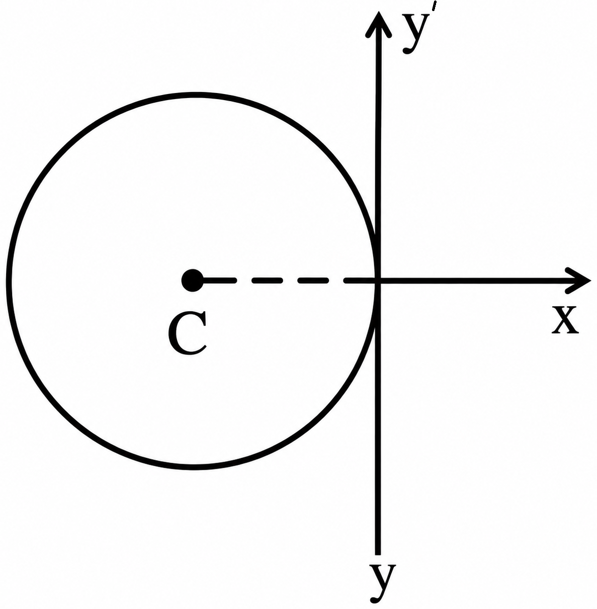
- A thin wire of length ' \(L\) ' and linear mass density ' \(m\) ' is bent into a circular ring (in \(x-y\) plane) with centre ' \(C^{\prime}\) as shown in figure. The moment of inertia of the ring about an axis \(y y^{\prime}\) will be :
 NEET 2026 Hard
 - A standard filament lamp consumes \(100\,W\) when connected to \(200\,V\) ac mains supply. The peak current through the bulb will be \(........\,A\)NEET 2022 Medium
- The net impedance of circuit (as shown in figure) will be \(...........\,\Omega\)
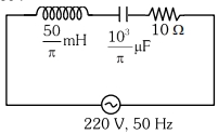 NEET 2023 Medium
 - Consider the following statements \((A)\) and \((B)\) and identify the correct answer. \((A)\) A zener diode is connected in reverse bias, when used as a voltage regulator. \((B)\) The potential barrier of \(\mathrm{p}-\mathrm{n}\) junction lies between \(0.1\, \mathrm{~V}\) to \(0.3 \,\mathrm{~V}\).NEET 2021 Medium
- The angular speed of the wheel of a vehicle is increased from \(360 \;rpm\) to \(1200 \;rpm\) in \(14 \;second\). Its angular acceleration is,NEET 2020 Medium
- The ratio of wavelengths of the last line of Balmer series and the last line of Lyman series isNEET 2017 Medium
More PYQs from NEET
- A ball of mass 0.5 kg is dropped from a height of 40 m. The ball hits the ground and rises to a height of 10 m. The impulse imparted to the ball during its collision with the ground is ....Take \((g =9.8 m / s ^2)\)NEET 2025 Medium
- Which of the following molecules has the maximum dipole moment ?NEET 2014 Medium
- Which one of the following matches is correct ?
Mucor Reproduction by Conjugation Ascomycetes Agaricus Parasitic fungus Basidiomycetes Phytophthora Aseptate mycelium Basidiomycetes Alternaria Sexual reproduction absent Deuteromycetes NEET 2015 Medium - In which one of the following processes \(CO_2\) is not released?NEET 2014 Medium
- In a plant, black seed color \((\mathrm{BB} / \mathrm{BB})\) is dominant over white seed color (\(bb\)). In order to find out the genotype of the black seed plant, with which of the following genotype will you cross it?NEET 2024 Medium
- In which of the following, gametophyte is not independent free living ?NEET 2015 Medium