MHT CET · Physics · Semiconductors
To get the truth table shown, from the following logic circuit, the Gate \(\mathrm{G}\) should be
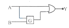
\(\begin{array}{|c|c|c|}\hline\mathrm{A} & \mathrm{B} & \mathrm{Y} 0 & 0 & 0 0 & 1 & 0 1 & 0 & 1 1 & 1 & 1\\\hline\end{array}\)
- A OR
- B AND
- C NOR
- D NAND
Answer & Solution
Correct Answer
(B) AND
Step-by-step Solution
Detailed explanation
Truth table for \(\mathrm{Y}\), with the possible values of \(\mathrm{C}\) is,
\(\begin{array}{|c|c|c|}
\hline \mathbf{A} & \mathbf{C} & \mathbf{Y} \\
\hline 0 & 0 & 0 \\
\hline 0 & 0 & 0 \\
\hline 1 & 0,1 & 1 \\
\hline 1 & 0,1 & 1 \\
\hline
\end{array}\)
For gate \(\mathrm{G}\)
\(\begin{array}{|c|c|c|c|}
\hline & A & B & C \\
\hline (I) & 0 & 0 & 0 \\
\hline (II) & 0 & 1 & 0 \\
\hline (III) & 1 & 0 & 0,1 \\
\hline (IV) & 1 & 1 & 0,1 \\
\hline
\end{array}\)
\(\mathrm{G}\) is not a NOT gate as NOT gate takes only one input. (II) indicates \(\mathrm{G}\) is not a OR gate as OR gate would give high output for the inputs in (II). Also, (II) indicates it is not a XOR gate as XOR would also give high output for inputs in (II). Hence, the given truth table is satisfied only by AND gate.
See the Complete Solution
Get step-by-step explanations for this and 2.5 Lakh+ more JEE, NEET & CET questions.
- Unlock all solutions
- Practice the full chapter
- Track accuracy across PYQs
4.8 rated on Google Play · 14,000+ reviews
More questions from Physics
- If the potential difference used to accelerate electrons is increased four times, by what factor does the de-Broglie wavelength associated with the electrons change?MHT CET 2024 Medium
- A body travelling with uniform acceleration crosses two points A and B with velocities \(20 \mathrm{~m} / \mathrm{s}\) and \(30 \mathrm{~m} / \mathrm{s}\) respectively. The speed of the body at mid point of A and B is (nearly)MHT CET 2024 Easy
- In potentiometer experiments, two cells of e. m. f. ' \(E_1\) ' and ' \(E_2\) ' are connected in series \(\left(E_1>E_2\right)\), the balancing length is \(64 \mathrm{~cm}\) of the wire. If the polarity of \(E_2\) is reversed, the balancing length becomes \(32 \mathrm{~cm}\). The ratio \(\mathrm{E}_1 / \mathrm{E}_2\) isMHT CET 2023 Medium
- A galvanometer of resistance \(G\) can be converted into a voltmeter of range \(V\) by connecting a resistance \(R\) in series with it. The series resistance required to change its range to \(\frac{V}{3}\) isMHT CET 2022 Hard
- Four point charges each \(+q\) is placed on the circumference of a circle of diameter 2 d in such a way that they form a square. The potential at the centre is proportional toMHT CET 2024 Medium
- The power factor of a CR circuit is \(\frac{1}{\sqrt{2}}\), If the frequency of a. c. signal is halved, then the power factor of the circuit will becomeMHT CET 2025 Medium
More PYQs from MHT CET
- The approximate value of isMHT CET 2016 Medium
- A closely wound coil of 100 turns and of crosssection \(1 \mathrm{~cm}^2\) has coefficient of self inductance 1 mH . The magnetic induction at the centre of the core of a coil when a current of 2 A flows in it, will be (in \(\mathrm{Wb} / \mathrm{m}^2\) )MHT CET 2024 Medium
- An object is cooled from \(75^{\circ} \mathrm{C}\) to \(65^{\circ} \mathrm{Cin} 2 \mathrm{~min}\). The time, it takes to cool from \(55^{\circ} \mathrm{C}\) to \(45^{\circ} \mathrm{Cis}\) [The temperature of surrounding is \(30^{\circ} \mathrm{C}\) ]MHT CET 2022 Easy
- The approximate value of \(\sin \left(60^{\circ} 0^{\prime} 10^{\prime \prime}\right)\) is (given that \(\sqrt{3}=1.732,1^{\circ}=0.0175^{\mathrm{C}}\) )MHT CET 2023 Easy
- Four electric charges \(+q,+q,-q\) and \(-q\) are placed in order at the corners of a square of side \(2 r\). The electric potential at a point midway between the two negative charges isMHT CET 2022 Hard
- If \(\mathrm{R}=\{(a, \mathrm{~b}) / \mathrm{b}=a-1, a \in \mathrm{Z}, 5 < a < 9\}\), then the range of \(\mathrm{R}\) isMHT CET 2020 Easy