MHT CET · Physics · Semiconductors
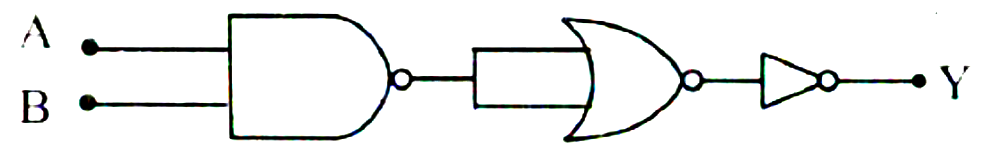
The logic circuit in figure is equivalent to
- A OR gate
- B AND gate
- C NOR gate
- D NAND gate
Answer & Solution
Correct Answer
(D) NAND gate
Step-by-step Solution
Detailed explanation
The output of the NAND gate will be \(\overline{\mathrm{A} \cdot \mathrm{B}}\).
The output of the NOR gate will be
\(\overline{\overline{\bar{A} \cdot \mathrm{~B}}+\overline{\overline{\mathrm{A} \cdot \mathrm{~B}}}}=\mathrm{A} \cdot \mathrm{~B}\)
The output of the NOT gate will be \(\overline{\mathrm{A} \cdot \mathrm{B}}\) Thus, the given network is equivalent to a NAND gate.
The output of the NOR gate will be
\(\overline{\overline{\bar{A} \cdot \mathrm{~B}}+\overline{\overline{\mathrm{A} \cdot \mathrm{~B}}}}=\mathrm{A} \cdot \mathrm{~B}\)
The output of the NOT gate will be \(\overline{\mathrm{A} \cdot \mathrm{B}}\) Thus, the given network is equivalent to a NAND gate.
See the Complete Solution
Get step-by-step explanations for this and 2.5 Lakh+ more JEE, NEET & CET questions.
- Unlock all solutions
- Practice the full chapter
- Track accuracy across PYQs
4.8 rated on Google Play · 14,000+ reviews
More questions from Physics
- A particle performs S.H.M. Its potential energies are 'U \(_{1}\) ' and \({ }^{\prime} \mathrm{U}_{2}\) ' at displacements
\({ }^{\prime} \mathrm{x}_{1}{ }^{\prime}\) and \({ }^{\prime} \mathrm{x}_{2}\) ' respectively. At displacement \(\left(\mathrm{x}_{1}+\mathrm{x}_{2}\right)\), its potential energy ' \(\mathrm{U}^{\prime}\) isMHT CET 2020 Easy - When the zener diode is used as voltage regulator, it is connected inMHT CET 2025 Easy
- A ray of light is incident at an angle ' \(\mathrm{i}\) ' on one face of thin prism. The ray emerges normally from the other face. Refractive index of the glass prism is ' \(n\) ' and angle of prism is ' \(A\) '. The value of ' \(i\) ' isMHT CET 2021 Easy
- A galvanometer has resistance ' \(G\) ' \(\Omega\) and ' \(I_g\) ' is current flowing through it which produces full scale deflection. ' \(S_1\) ' is the value of shunt which converts it into an ammeter of range 0 to ' \(3 I\) ' and ' \(S_2\) ' is the shunt value which converts it into an ammeter of range 0 to ' \(4 I\) ', the ratio \(S_2: S_1\) isMHT CET 2021 Medium
- The average value of a.c. voltage is given by \(\mathrm{V}=\mathrm{V}_{\mathrm{m}} \sin (\omega \mathrm{t})\) over time interval \(t=0\) to \(=\frac{\pi}{\omega}\) isMHT CET 2022 Easy
- The magnetic field at the centre of a current carrying circular coil of an area ' \(A\) ' is ' \(B\) '. The magnetic moment of the coils is
[ \(\mu 0=\) permeability of free space.]MHT CET 2022 Hard
More PYQs from MHT CET
- If \(\tan \theta=2\) and \(\theta\) lies in the third quadrant, then the value of \(\sec \theta\) isMHT CET 2020 Easy
- What type of following solids the ice is?MHT CET 2023 Easy
- If \(\mathrm{K}_{\mathrm{sp}}\) is solubility product of \(\mathrm{Al}(\mathrm{OH})_3\), its solubility is expressed by formula,MHT CET 2023 Easy
- Which among the following statements is TRUE about gammexane?MHT CET 2023 Easy
- If \(A=\left[\begin{array}{ccc}1 & 0 & 2 \\ -1 & 1 & -2 \\ 0 & 2 & 1\end{array}\right]\), adj \(A=\left[\begin{array}{ccc}5 & x & -2 \\ 1 & 1 & 0 \\ -2 & -2 & y\end{array}\right]\), then value of \(\mathrm{x}+\mathrm{y}\) isMHT CET 2021 Easy
- Identify product B in following reaction.
Acetanilide \(\frac{\text { conc. } \mathrm{HNO}_{3}}{\text { conc. } \mathrm{H}_{2} \mathrm{SO}_{4}}\) A \(\frac{\mathrm{H}^{+}}{\text {or } \mathrm{OH}^{-}} \mathrm{B}\)MHT CET 2020 Medium